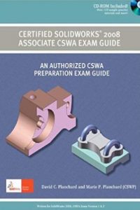
Certified SolidWorks 2008 Associate CSWA Exam Guide 2nd Edition
AN AUTHORIZED CSWA PREPARATION EXAM GUIDE
David C. PLnchard and Marie P. PLnchard
Chapter 1: SolidWorks 2008 User Interface
Reviews the SolidWorks 2008 User Interface and CommandManager:
Menu bar toolbar, Menu bar menu, Drop-down menus, Context toolbars,
Consolidated drop-down toolbars, System feedback icons, Confirmation Corner,
Heads-up View toolbar, and more.
Chapter 2: Basic Theory and Drawing Theory (2 Questions – Total 10 Points)
• Identify and apply basic concepts in SolidWorks
• Recognize 3D modeling techniques:
• Understand how parts, assemblies, and drawings are related
• Identify the feature type, parameters, and dimensions
• Identify the correct standard reference planes: Top, Right, and Front
tIntroduction
Page I – 3
• Determine the design intent for a model
• Identify and understand the procedure for the following:
• Assign and edit material to a part
• Apply the Measure tool to a part or an assembly
• Locate the Center of mass, and Principal moments of inertia relative to the
default coordinate location, Origin.
• Calculate the overall mass and volume of a part
• Recognize and know the function and elements of the Part and Assembly
FeatureManager design tree:
• Sketch status
• Component status and properties
• Display Pane status
• Reference configurations
• Identify the default Sketch Entities from the Sketch toolbar: Line, Rectangle,
Circle, etc.
• Identify the default Sketch Tools from the Sketch toolbar: Fillet, Chamfer,
Offset Entities, etc.
• Identify the available SolidWorks File formats for input and export:
• Save As type for a part, assembly, and drawing
• Open File of different formats
• Use SolidWorks Help:
• Contents, Index, and Search tabs
• Identify the process of creating a simple drawing from a part or an assembly:
• Knowledge to insert and modify the 3 Standard views
• Knowledge to add a sheet and annotations to a drawing
• Recognize all drawing name view types by their icons:
• Model, Projected, Auxiliary, Section, Aligned Section, Detail, Standard,
Broken-out Section, Break, Crop, and Alternate Position
• Identify the procedure to create a named drawing view:
• Model, Projected, Auxiliary, Section, Aligned Section, Detail, Standard,
Broken-out Section, Break, Crop, and Alternate PositionIntroduction
Page I – 4
• Specify Document Properties:
• Select Unit System
• Set Precision
Chapter 3: Part Modeling (1 Question – Total 30 Points)
• Read and understand an Engineering document:
• Identify the Sketch plane, part Origin location, part dimensions, geometric
relations, and design intent of the sketch and feature
• Build a part from a detailed dimensioned illustration using the following
SolidWorks tools and features:
• 2D & 3D sketch tools
• Extruded Boss/Base
• Extruded Cut
• Fillet
• Mirror
• Revolved Base
• Chamfer
• Reference geometry
• Plane
• Axis
• Calculate the overall mass and volume of the created part
• Locate the Center of mass for the created part relative to the Origin
Chapter 4: Advanced Part Modeling (1 Question -Total 20 Points)
• Specify Document Properties
• Interpret engineering terminology:
• Create and manipulate a coordinate system
• Build an advanced part from a detailed dimensioned illustration using the
following tools and features:
• 2D & 3D Sketch tools
• Extruded Boss/Base
• Extruded CutIntroduction
Page I – 5
• Fillet
• Mirror
• Revolved Boss/Base
• Linear & Circular Pattern
• Chamfer
• Revolved Cut
• Locate the Center of mass relative to the part Origin
• Create a coordinate system location
• Locate the Center of mass relative to a created coordinate system
Chapter 5: Assembly Modeling (1 Question – Total 30 Points)
• Specify Document Properties
• Identify and build the components to construct the assembly from a detailed
illustration using the following features:
• Extruded Boss/Base
• Extruded Cut
• Fillet
• Mirror
• Revolved Boss/Base
• Revolved Cut
• Linear Pattern
• Chamfer
• Hole Wizard
• Identify the first fixed component in an assembly
• Build a bottom-up assembly with the following Standard mates:
• Coincident, Concentric, Parallel, Perpendicular, Tangent, Angle, and
Distance
• Aligned, Anti-Aligned options
• Apply the Mirror Component tool
• Locate the Center of mass relative to the assembly Origin
• Create a coordinate system locationIntroduction
Page I – 6
• Locate the Center of mass relative to a created coordinate system
• Calculate the overall mass and volume for the created assembly
• Mate the first component with respect to the assembly reference planes
Chapter 6: Advanced Modeling Theory and Analysis (2 Questions – Total 10
Points)
• Understand basic Engineering analysis definitions
• Knowledge of the COSMOSXpress Wizard interface
• Ability to apply COSMOSXpress to a simple part
In SolidWorks 2009, COSMOSXpress is called SimulationXpress.
كلمة سر فك الضغط : books-world.net
The Unzip Password : books-world.net
تحميل
يجب عليك التسجيل في الموقع لكي تتمكن من التحميل
تسجيل | تسجيل الدخول


